
Original illustrated assembly manual (PDF)
Download the supplied 27-page reference for the identified Model 300 and Model 400 systems. This historical source does not replace current, manufacturer-approved instructions for your exact equipment.
Section 1
Scope and safety notice
This guide concerns the specifically identified Model 300 and Model 400 fiberglass mobile scaffold systems. It is an educational navigation reference based on the supplied assembly manual, not an authorization to assemble, modify or operate a tower. Verify the current manufacturer-approved instructions, exact components, site conditions and applicable requirements with a competent person.
Section 2
Model 300 versus Model 400: access
The supplied manual distinguishes the models primarily by access arrangement. Model 300 describes designated interior frame-rung access; Model 400 describes internal ladders at the relevant levels and travel through platform trapdoors. Do not transfer an access method from one model to another. See the source manual introduction and assembly stage 7.
Section 3
Identify the tower components
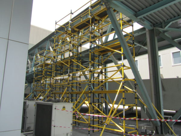
The manual identifies locking casters, adjustable legs, horizontal and diagonal braces, lateral frames, platforms with trapdoors, guardrail frames, toe boards, interlock clips, windlocks and outriggers. Its component illustrations distinguish single-width and double-width towers. Check component identification, compatibility, condition and completeness before beginning work.
Section 4
The 14 assembly stages in the supplied manual
Stages 1–4 identify braces, prepare the caster-and-leg base, connect the initial horizontal brace and opposite lateral frame. Stages 5–6 add diagonal bracing and verify level and alignment. Stages 7–8 address model-specific access and platform placement. Stages 9–10 address stabilizers and additional frames, clips and braces. Stage 11 addresses additional levels and access; stages 12–13 address guardrail frames and horizontal guardrail braces. Stage 14 addresses toe boards, platform windlocks, casters and final inspection. This outline intentionally omits operational measurements and fastening instructions: use the complete approved illustrated manual for the actual erection sequence.
Section 5
System-specific load and height information
The supplied manual lists a maximum of 550 lb per platform, 790 lb per double-width level and 1,590 lb per tower. Its height table distinguishes single- and double-width towers and indoor/outdoor placement. These values are historical source specifications for the covered systems only; obtain written confirmation of the actual delivered configuration, rated loads and permitted heights. Never use this table to rate another fiberglass tower.
Section 6
Outriggers, wind and stability
The supplied guide describes outriggers and stabilizer placement, weather considerations and wind precautions. Stability depends on the complete tower, ground support, height, loading and site conditions. Do not use a generic height-to-base ratio or wind number as a substitute for the current model-specific requirements and a site assessment.
Section 7
Before-use inspection
The manual provides a checklist covering stable and level support, caster locks, outriggers, access, diagonal and horizontal braces, platforms, windlocks, interlock clips, guardrails, toe boards, clamps and overhead electrical hazards. A competent person must evaluate defects and authorize corrective action before use.
Section 8
Dismantling and moving the tower
The supplied manual addresses reversing the assembly sequence, protecting the work area, lowering components without throwing them and checking stability after relocation. Do not move a tower with people or unsecured tools on it. Follow current manufacturer directions and applicable mobile-scaffold rules.
Section 9
Regulatory references and technical verification
For U.S. construction work, consult OSHA 29 CFR 1926.451, 1926.452(w) for mobile scaffolds, and 1926.454 for training. The source PDF cites an older ANSI edition; do not treat that citation as confirmation of the currently applicable consensus standard. Fiberglass material properties do not remove electrical-clearance requirements.
Section 10
Request the approved manual and a configuration review
Provide the model number, width, intended platform height, application, worksite conditions and existing component identification. Our team can help identify the correct documentation and next steps for a system-specific quote.
Primary references
Official sources and further reading
Use the links below to review the original source and confirm the current requirement, revision and applicability.